Gil Zweig, President, Glenbrook Technologies01.29.20
Over the years, the U.S. Food and Drug Administration (FDA) has issued documents that provide guidance for industry and FDA staff regarding application of X-ray inspection procedures in medical device testing. The particular focus of these documents has been on cardiovascular devices, including intravascular stents and associated delivery systems.
Document number 1545, issued on April 18, 2010, addressed “Non-Clinical Engineering Tests and Recommended Labeling for Intravascular Stents and Associated Delivery Systems.” The issue of radiopacity of the stent is addressed in this document in section B.14 with the recommendation the manufacturer provide indication of the stent radiological visibility: “FDA recommends that you evaluate the radiopacity of your stent at the smallest diameter and the shortest length during the following stages in the life of the stent:
Data to be provided indicating radiological visibility using animal or in vitro phantom implants.”
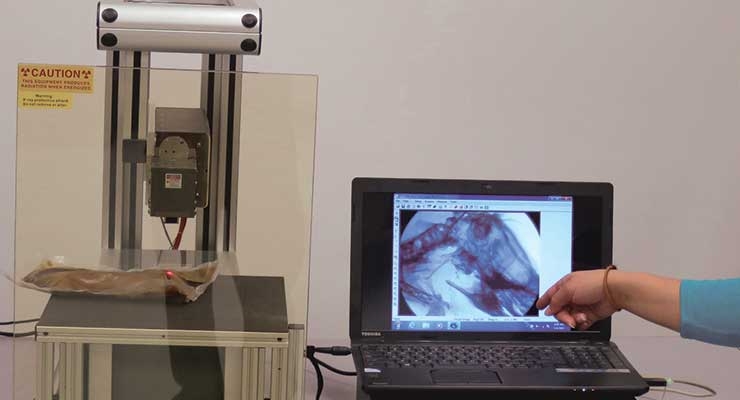
Document number 1717, issued on July 29, 2010, addressed “General Considerations for Animal Studies for Cardiovascular Devices.” In the section on “Post-Mortem Imaging and Assessment Methods,” the following is stated: “Explant Radiography—Prior to preparing devices for histomorphometric analysis, you should consider whether an analysis of the structural integrity of the device would assist in the determination of device safety. For devices that are implanted in coronary arteries or intra-cardiac locations such as coronary artery stents or prosthetic heart valves, you should consider the use of device radiography for explanted whole hearts,” (Figure 1).
Evaluating Device Radiopacity
Different materials exhibit different radiopacity as a function of material composition (i.e. atomic weight) and thickness; it is additionally influenced by the anode voltage of the X-ray source. It is important to note an object of high radiopacity can veil the details of an object of low radiopacity, regardless of whether one object is in front of or behind the other.
Stent development offers an example of designing for X-ray inspection of devices used in angiographic procedures (Figure 2). The difference in radiopacity can be seen in the fluoroscopic images of nitinol (nickel-titanium) and stainless steel stents deployed into an animal model. The nitinol stent will present visibly less radiopacity than the stainless steel stent, requiring the nitinol stent to have platinum markers on the tips for fluoroscopic detection. Because radiopacity is a function of the atomic weight of the device’s constituent elements, the platinum tips, having higher atomic weight, add radiopacity.
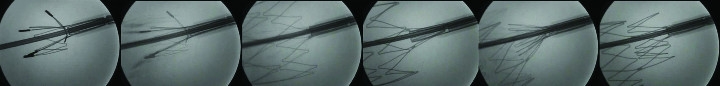
Figure 2: In the development of stents, high-resolution magnification fluoroscopy permits the observation and fluoroscopic video recording of the stent deployment as an “x-ray movie.”
In addition, stent wire breaks following fatigue testing can be detected with magnification fluoroscopy. For this application, the detection of the break requires observing the stent with dynamic micro-fluoroscopy as the stent is slowly rotated. In this way, the complete wire structure can be observed and recorded. Micro-fluoroscopy is also presently being used in small animal, pre-clinical research.
In performing radiopacity evaluation, it is important to note the apparent radiopacity of a device is influenced by the setting of the X-ray source anode voltage.
Conclusion
FDA guidelines suggest the use of X-ray inspection for the determination of the radiopacity of intravascular stents and delivery systems. The resulting images and their interpretation will depend upon the methodology and X-ray systems employed, as well as an understanding of the factors that influence the appearance of the X-ray image.
Gil Zweig is president of Glenbrook Technologies, which manufactures magnification fluoroscopy X-ray systems, such as the LabScope, which is presently in use at numerous research hospitals, medical device companies, and university research facilities.
Document number 1545, issued on April 18, 2010, addressed “Non-Clinical Engineering Tests and Recommended Labeling for Intravascular Stents and Associated Delivery Systems.” The issue of radiopacity of the stent is addressed in this document in section B.14 with the recommendation the manufacturer provide indication of the stent radiological visibility: “FDA recommends that you evaluate the radiopacity of your stent at the smallest diameter and the shortest length during the following stages in the life of the stent:
- Delivery
- Deployment if separate from delivery
- After implantation.
Data to be provided indicating radiological visibility using animal or in vitro phantom implants.”
Document number 1717, issued on July 29, 2010, addressed “General Considerations for Animal Studies for Cardiovascular Devices.” In the section on “Post-Mortem Imaging and Assessment Methods,” the following is stated: “Explant Radiography—Prior to preparing devices for histomorphometric analysis, you should consider whether an analysis of the structural integrity of the device would assist in the determination of device safety. For devices that are implanted in coronary arteries or intra-cardiac locations such as coronary artery stents or prosthetic heart valves, you should consider the use of device radiography for explanted whole hearts,” (Figure 1).
Evaluating Device Radiopacity
Different materials exhibit different radiopacity as a function of material composition (i.e. atomic weight) and thickness; it is additionally influenced by the anode voltage of the X-ray source. It is important to note an object of high radiopacity can veil the details of an object of low radiopacity, regardless of whether one object is in front of or behind the other.
Stent development offers an example of designing for X-ray inspection of devices used in angiographic procedures (Figure 2). The difference in radiopacity can be seen in the fluoroscopic images of nitinol (nickel-titanium) and stainless steel stents deployed into an animal model. The nitinol stent will present visibly less radiopacity than the stainless steel stent, requiring the nitinol stent to have platinum markers on the tips for fluoroscopic detection. Because radiopacity is a function of the atomic weight of the device’s constituent elements, the platinum tips, having higher atomic weight, add radiopacity.
Figure 2: In the development of stents, high-resolution magnification fluoroscopy permits the observation and fluoroscopic video recording of the stent deployment as an “x-ray movie.”
In addition, stent wire breaks following fatigue testing can be detected with magnification fluoroscopy. For this application, the detection of the break requires observing the stent with dynamic micro-fluoroscopy as the stent is slowly rotated. In this way, the complete wire structure can be observed and recorded. Micro-fluoroscopy is also presently being used in small animal, pre-clinical research.
In performing radiopacity evaluation, it is important to note the apparent radiopacity of a device is influenced by the setting of the X-ray source anode voltage.
Conclusion
FDA guidelines suggest the use of X-ray inspection for the determination of the radiopacity of intravascular stents and delivery systems. The resulting images and their interpretation will depend upon the methodology and X-ray systems employed, as well as an understanding of the factors that influence the appearance of the X-ray image.
Gil Zweig is president of Glenbrook Technologies, which manufactures magnification fluoroscopy X-ray systems, such as the LabScope, which is presently in use at numerous research hospitals, medical device companies, and university research facilities.
