Kenneth MacCallum, P.Eng., Principal Engineering Physicist, StarFish Medical08.30.21
I mentioned to my brother I was writing a blog about closed-loop temperature control—his initial response was "boring!" then he peppered me with a ton of questions about managing heat in an AC inverter he's designing. I fear this topic isn’t at the top of everyone's interests list, yet we seem to bump into it regularly when developing medical devices.
Maybe an assay needs to be temperature regulated. Or the spectral output of an LED or laser has a large tempco. Or it's to push down the noise floor of a sensor. Sometimes closed-loop temperature control is just a nice way to keep a heatsink cool without having fans blasting continuously. In all these cases, a closed-loop feedback approach is an effective mechanism to address the thermal control challenges.
Sensing Temperature
The first step of the design process is to choose a sensor. There are plenty to choose from and I have some favorites.
My first choice for thermal sensors is thermistors. They’re inexpensive and can be sourced as both PCB-mounted and leaded devices. They’re small and very stable. (You can read my previous blog on the subject here.)
Another option is resistance temperature detectors (RTD). These are highly linear and well understood by calibration laboratories. This means they can be sent out for calibration individually, which is sometimes handy. They’re usually large and fairly pricy.
A less favorite option of mine is to use a temperature sensing IC. They’re available with either analogue or digital outputs, which is often convenient. The reason I don't love them is they don't often solve problems better than thermistors; they add yet another single-sourced component to the design.
By far my last choice is thermocouples—they're a pain to amplify and linearize. Their signals are tiny. They're not PCB mountable and not very cheap. That said, they do often work at higher temperatures than other sensors.
Whichever sensor you choose, there will be some circuitry required to turn that signal into something useful. (I'll leave that bit to you.)
Moving Heat
Now that we've selected a sensor, we need to pick the most appropriate method to create or move heat.
If the application only needs heat added, then a simple resistive heater is the right solution. This can be implemented with resistors or simply as PCB traces. Note if you want to linearly control the current—say, with a transistor—you can make use of the thermal losses in the transistor too!
If you only need to remove heat, for instance to keep a heatsink cool, a fan may be an acceptable solution. It's usually possible to source a fan with a PWM speed control without too much impact on cost. That allows for a more sophisticated control strategy and less audible noise from the fan.
Finally, if you need to heat and cool, or want to avoid the noise of a fan, you can use a Peltier device. If you truly want bidirectional heat control, you’ll need to drive it with an H-bridge. There’s also the added complexity of providing the conductive heat paths to and from the Peltier.
How to Implement with PCBs
My favorite design philosophy is to make the most of my PCBs. (I mention this in this ancient blog.)
It’s often easily possible to ensure all thermal control elements are on one or two PCBs. When measuring the temperature of something, why not screw it to the PCB? If I want to heat something with a resistor, again, why not screw it to a PCB?
If we need to get a bunch of heat out of a component like a high-power LED, using an aluminum-backed PCB works well when mounted to a heatsink. A thermistor can be mounted on the board to sense the LED temperature.
If we don't have an awesomely conductive PCB substrate, using a thermal "island" works well to ensure a thermistor conducts to a heatsink and not parasitically across the board.
Side note, when I use the term heatsink, I mean a place I can dump (or extract) heat. I don't necessarily mean an extruded, finned, aluminum component for convecting heat from electronics. Any structural element of our design that can conduct heat to or from somewhere safe can be a heatsink. Make it out of aluminum and do some quick calculations to ensure the delta T isn't unacceptable. Often, the baseplate or backplate of a device enclosure works fine, depending on the heat load.
Control Strategy
Now that we've designed the system’s hardware, what about the control strategy?
I tend to stay away from bang-bang control, where you blast the heat when too cold and turn it off when it gets too hot. If you've made the effort to sense the temperature and you have the ability to continuously vary the drive, why not smooth out the excursions and minimize the following error?
In my experience, thermal control loops are effectively addressed using a PI controller. That means the control output is a combination of a proportional term and an integral term. The proportional term gives a quick, hard response to a large error and the integral term gradually shrinks the error to zero.
I'm not usually a fan of tuning by knob twiddling, but in the case of thermal control loops it usually gets you close enough. I like to think of a PI controller as a gain times a zero times an integrator. At high frequency the gain is the P coefficient. At low frequency, it drops from infinity at 20dB/dec like an integrator. They meet at the 3dB frequency, the time constant of which is the P coefficient over the I coefficient. Likely your thermal system is really slow, so the controller’s time constant should be slow too. I'd suggest many seconds or many tens of seconds.
With any real control system, there are times the input or the output is bounded by circuit limitations. A bounded input is usually not so bad, it just holds things back a bit. A bounded output is bad for another reason related to the integral term: wind-up.
If the controller’s output hits its bounds, the integral term will grow without the output growing. By the time the setpoint is reached, the integrator is so wound up it badly overshoots. A typical controller implementation usually includes a mechanism to limit the integrator when the output limits.
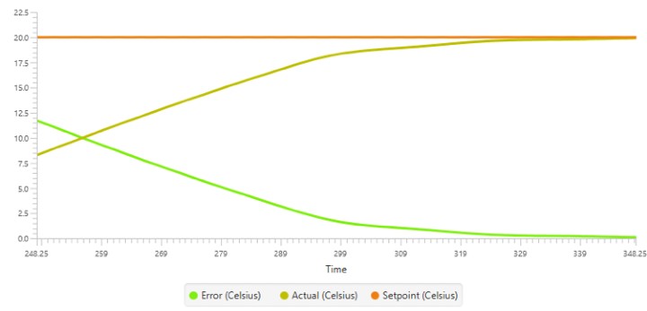
The actual response of a system with thermally stabilized LEDs. You can see where the outputs stop saturating. Isn’t that satisfying?
Implementing in Analog
One way to implement the controller is to use an op-amp. A PI loop is formed with a resistor and capacitor in series in the feedback path.
Minimizing windup in this analogue implementation may happen naturally. If the total swing of the op-amp usefully modulates the output, the integrator will pin at the rails, as desired.
I'll leave it up to you to design the circuit to convert the op-amp output to a useful control signal for your heat control device—whether it's a resistive heater, a PWM driven fan, or Peltier.
Implementing in Firmware
Another option to implement a feedback controller is to compute it in firmware. This is convenient if you already have a microcontroller. Interfacing sensors and drives to the microcontroller is typically pretty simple.
The first thing I'd suggest is to convert the temperature signal into a meaningful value in the firmware. This isn't strictly necessary, but it often becomes confusing when computing with all these arbitrarily scaled values.
My go-to approach to feedback controllers in firmware is a z-transform difference equation. I start with the biquad form and go from there. With a PI controller, most of the biquad coefficients are trivial. The reason I like this approach is because pinning the integral is really easy. If my computed newest output is out of bounds, I simply clip it. This clipped value propagates through the delays. I find this method an easy and effective way to limit the impact of windup. This works for PI controllers and also for more complex control strategies.
One thing to keep in mind with medical devices: if you have a moderate or major severity risk of harm related to the temperature controlled with firmware, there should likely be a hardware mechanism to shut things down when limits are exceeded. Everyone will be happier if you keep that functionality out of firmware!
I hope you've found a useful tip or two in this blog. I know it's not initially the most gripping topic, but it comes up so regularly in medical device development it's worth talking about. I find it pretty satisfying after designing the control system to watch the following error growing steadily smaller as the setpoint is achieved.
Kenneth MacCallum, P.Eng., is the principal engineering physicist at StarFish Medical.
Maybe an assay needs to be temperature regulated. Or the spectral output of an LED or laser has a large tempco. Or it's to push down the noise floor of a sensor. Sometimes closed-loop temperature control is just a nice way to keep a heatsink cool without having fans blasting continuously. In all these cases, a closed-loop feedback approach is an effective mechanism to address the thermal control challenges.
Sensing Temperature
The first step of the design process is to choose a sensor. There are plenty to choose from and I have some favorites.
My first choice for thermal sensors is thermistors. They’re inexpensive and can be sourced as both PCB-mounted and leaded devices. They’re small and very stable. (You can read my previous blog on the subject here.)
Another option is resistance temperature detectors (RTD). These are highly linear and well understood by calibration laboratories. This means they can be sent out for calibration individually, which is sometimes handy. They’re usually large and fairly pricy.
A less favorite option of mine is to use a temperature sensing IC. They’re available with either analogue or digital outputs, which is often convenient. The reason I don't love them is they don't often solve problems better than thermistors; they add yet another single-sourced component to the design.
By far my last choice is thermocouples—they're a pain to amplify and linearize. Their signals are tiny. They're not PCB mountable and not very cheap. That said, they do often work at higher temperatures than other sensors.
Whichever sensor you choose, there will be some circuitry required to turn that signal into something useful. (I'll leave that bit to you.)
Moving Heat
Now that we've selected a sensor, we need to pick the most appropriate method to create or move heat.
If the application only needs heat added, then a simple resistive heater is the right solution. This can be implemented with resistors or simply as PCB traces. Note if you want to linearly control the current—say, with a transistor—you can make use of the thermal losses in the transistor too!
If you only need to remove heat, for instance to keep a heatsink cool, a fan may be an acceptable solution. It's usually possible to source a fan with a PWM speed control without too much impact on cost. That allows for a more sophisticated control strategy and less audible noise from the fan.
Finally, if you need to heat and cool, or want to avoid the noise of a fan, you can use a Peltier device. If you truly want bidirectional heat control, you’ll need to drive it with an H-bridge. There’s also the added complexity of providing the conductive heat paths to and from the Peltier.
How to Implement with PCBs
My favorite design philosophy is to make the most of my PCBs. (I mention this in this ancient blog.)
It’s often easily possible to ensure all thermal control elements are on one or two PCBs. When measuring the temperature of something, why not screw it to the PCB? If I want to heat something with a resistor, again, why not screw it to a PCB?
If we need to get a bunch of heat out of a component like a high-power LED, using an aluminum-backed PCB works well when mounted to a heatsink. A thermistor can be mounted on the board to sense the LED temperature.
If we don't have an awesomely conductive PCB substrate, using a thermal "island" works well to ensure a thermistor conducts to a heatsink and not parasitically across the board.
Side note, when I use the term heatsink, I mean a place I can dump (or extract) heat. I don't necessarily mean an extruded, finned, aluminum component for convecting heat from electronics. Any structural element of our design that can conduct heat to or from somewhere safe can be a heatsink. Make it out of aluminum and do some quick calculations to ensure the delta T isn't unacceptable. Often, the baseplate or backplate of a device enclosure works fine, depending on the heat load.
Control Strategy
Now that we've designed the system’s hardware, what about the control strategy?
I tend to stay away from bang-bang control, where you blast the heat when too cold and turn it off when it gets too hot. If you've made the effort to sense the temperature and you have the ability to continuously vary the drive, why not smooth out the excursions and minimize the following error?
In my experience, thermal control loops are effectively addressed using a PI controller. That means the control output is a combination of a proportional term and an integral term. The proportional term gives a quick, hard response to a large error and the integral term gradually shrinks the error to zero.
I'm not usually a fan of tuning by knob twiddling, but in the case of thermal control loops it usually gets you close enough. I like to think of a PI controller as a gain times a zero times an integrator. At high frequency the gain is the P coefficient. At low frequency, it drops from infinity at 20dB/dec like an integrator. They meet at the 3dB frequency, the time constant of which is the P coefficient over the I coefficient. Likely your thermal system is really slow, so the controller’s time constant should be slow too. I'd suggest many seconds or many tens of seconds.
With any real control system, there are times the input or the output is bounded by circuit limitations. A bounded input is usually not so bad, it just holds things back a bit. A bounded output is bad for another reason related to the integral term: wind-up.
If the controller’s output hits its bounds, the integral term will grow without the output growing. By the time the setpoint is reached, the integrator is so wound up it badly overshoots. A typical controller implementation usually includes a mechanism to limit the integrator when the output limits.
The actual response of a system with thermally stabilized LEDs. You can see where the outputs stop saturating. Isn’t that satisfying?
Implementing in Analog
One way to implement the controller is to use an op-amp. A PI loop is formed with a resistor and capacitor in series in the feedback path.
Minimizing windup in this analogue implementation may happen naturally. If the total swing of the op-amp usefully modulates the output, the integrator will pin at the rails, as desired.
I'll leave it up to you to design the circuit to convert the op-amp output to a useful control signal for your heat control device—whether it's a resistive heater, a PWM driven fan, or Peltier.
Implementing in Firmware
Another option to implement a feedback controller is to compute it in firmware. This is convenient if you already have a microcontroller. Interfacing sensors and drives to the microcontroller is typically pretty simple.
The first thing I'd suggest is to convert the temperature signal into a meaningful value in the firmware. This isn't strictly necessary, but it often becomes confusing when computing with all these arbitrarily scaled values.
My go-to approach to feedback controllers in firmware is a z-transform difference equation. I start with the biquad form and go from there. With a PI controller, most of the biquad coefficients are trivial. The reason I like this approach is because pinning the integral is really easy. If my computed newest output is out of bounds, I simply clip it. This clipped value propagates through the delays. I find this method an easy and effective way to limit the impact of windup. This works for PI controllers and also for more complex control strategies.
One thing to keep in mind with medical devices: if you have a moderate or major severity risk of harm related to the temperature controlled with firmware, there should likely be a hardware mechanism to shut things down when limits are exceeded. Everyone will be happier if you keep that functionality out of firmware!
I hope you've found a useful tip or two in this blog. I know it's not initially the most gripping topic, but it comes up so regularly in medical device development it's worth talking about. I find it pretty satisfying after designing the control system to watch the following error growing steadily smaller as the setpoint is achieved.
Kenneth MacCallum, P.Eng., is the principal engineering physicist at StarFish Medical.